Terrain, Drawn Clean and Readable
GeoDrafts prepares topographic survey drawings from the terrain data you supply — organizing spot elevations, contours, breaklines, natural features, and constructed elements into a clear, consistent site plan.
Legend — Monuments
Each layer is a survey type — click one to open its page.
What This Service Covers
We structure supplied elevation data into readable contour layers, place spot levels and breaklines as instructed, draft natural and constructed features from your observations, and present everything with consistent symbols and a clear surface-reading hierarchy across the sheet set.
Terrain data is drafted as supplied. Surface interpretation, data capture, and professional verification remain with the responsible surveyor or engineer.

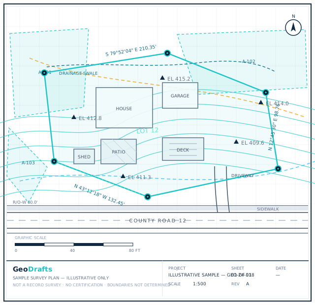

Topographic Survey Drafting, Layer by Layer
This service's layer is highlighted on the plan. Click other layers to explore the related survey types we draft.
Legend — Monuments
Survey Type · Contours
Topographic Survey Drafting
Drafting of terrain and site information, including supplied spot levels, contours, breaklines, natural features, and constructed elements, as appropriate to the project scope.
Click any layer on the plan — each one maps to a survey type we draft.
Typical Inputs
What we work from — all supplied by you.
- Spot level and elevation data supplied by the client
- Contour and breakline data (from field or photogrammetric sources)
- Feature observations and sketches
- Aerial or drone-derived surface files, where provided
- Client symbology, layering, and sheet standards
Deliverables & Formats
What you receive at handover.
- Topographic plan drawings with organized contour layers
- Spot elevation blocks placed per instructions
- Feature linework for natural and constructed elements
- PDF plots and editable CAD files
Where This Work Fits
Site design support packages for engineers
Planning and permit documentation prepared by the client
Volume and surface reference drawings as instructed
Baseline plans for development projects
How the Project Runs
Inspect terrain data
Supplied elevations, contours, and breaklines are reviewed.
Build the base plan
Surfaces and levels are organized into the agreed layer structure.
Draft features
Natural and constructed features are drawn from supplied observations.
Review against instructions
The sheet set is checked for completeness and readability.
Deliver files
Final drawings are delivered in the agreed formats.
Topographic Survey Drafting — Questions
Continue Exploring
Ready to Start Topographic Survey Drafting?
Share your project inputs and receive a scoped proposal.
Request a Quote